HowTo: Vialess MSL
In this howto guide, we will go through making a component called vialless MSL in RAIMAD. The purpose of the vialess MSL is to connect CPWs (coplanar waveguides) to a MSL (microstrip line). It's called "vialess" because the connection is made through electromagnetic coupling, thus requiring no holes (vias) in the substrate. For more information on this design, please consult On-Wafer Measurement of Microstrip-Based Circuits With a Broadband Vialess Transition by Lin Zhu and Kathleen L. Melde.
For this tutorial we will be designing a "toy" vialess MSL, meaning that while the structure will be similar to that of a real chip, the dimensions will not be to scale.
Tapered CPW Segment
First, let's start with a component that represents a CPW segment. Before we write any serious code, let's first define the Options and Marks annotations to have what we want. As you might remember from the RAIMAD Tutorial, annotations don't do much at runtime, but they help other programmers and tools understand what our component does. By writing the annotations first, we're setting up a framework for ourselves.
TODO we don't have a doc page on annotations
import raimad as rai

class CPWTaperMetal(rai.Compo):
    """
    Tapered CPW (positive image).

            |----- l ------|
                         __    _
                     __--  |  |
                 __--      |  |  gr1
        _    __--        __|  |_
    gl1  |  |      ___---     |  wr1
        _|  |___---    ____   |_
    wl1 _|   _____-----    |  |
    sl   |  |              |  |
        _|  |_____         |  |  sr
    wl2 _|   ___  -----____|  |_
    sl2  |  |   ---___        |  wr2
        _|  |__       ---__   |_
               --__        |  |
                   --__    |  |  gr2
                       --__|  |_
    """
    class Options:
        l = rai.Option.Geometric(
            "length of segment",
            )
        sl = rai.Option.Geometric(
            "width of signal line on the left",
            )
        sr = rai.Option.Geometric(
            "width of signal line on the right",
            )

        wl1 = rai.Option.Geometric(
            "width of top gap on the left",
            )
        wr1 = rai.Option.Geometric(
            "width of top gap on the right",
            )
        gl1 = rai.Option.Geometric(
            "width of top ground line on the left",
            )
        gr1 = rai.Option.Geometric(
            "width of top ground line on the right",
            )

        wl2 = rai.Option.Geometric(
            "width of bottom gap on the left (None to use wl1)",
            )
        wr2 = rai.Option.Geometric(
            "width of bottom gap on the right (None to use wr1)",
            )
        gl2 = rai.Option.Geometric(
            "width of bottom ground line on the left (None to use gl1)",
            )
        gr2 = rai.Option.Geometric(
            "width of bottom ground line on the right (None to use gr1)",
            )

    class Marks:
        tl_enter = rai.Mark("Start of CPW segment")
        tl_exit = rai.Mark("End of CPW segment")
Next, let's add the _make function.
class CPWTaperMetal(rai.Compo):
    ...

    class Options:
        ...

    class Marks:
        ...

    def _make(
            self,
            l: float,
            sl: float,
            sr: float,
            wl1: float,
            wr1: float,
            gl1: float,
            gr1: float,
            wl2: float | None = None,
            wr2: float | None = None,
            gl2: float | None = None,
            gr2: float | None = None,
            ):
        pass
Now, add some arithmetic that creates the signal line.
This is a component with a rather dense geometry,
so instead of using subcomponents,
we will access self.geoms directly.
This technique is covered in this
documentation page.
Since there is only one layer, we will call it root,
as per RAIMAD conventions.
class CPWTaperMetal(rai.Compo):
    ...

    class Options:
        ...

    class Marks:
        ...

    def _make(
            self,
            l: float,
            sl: float,
            sr: float,
            wl1: float,
            wr1: float,
            gl1: float,
            gr1: float,
            wl2: float | None = None,
            wr2: float | None = None,
            gl2: float | None = None,
            gr2: float | None = None,
            ):
        pass

        if wl2 is None: wl2 = wl1
        if wr2 is None: wr2 = wr1
        if gl2 is None: gl2 = gl1
        if gr2 is None: gr2 = gr1

        self.geoms.update({
            'root': [
                [  # Signal
                    (0, sl / 2),
                    (l, sr / 2),
                    (l, - sr / 2),
                    (0, - sl / 2),
                    ],
                ]
            })

# Let's test it right away

rai.show(CPWTaperMetal(l=10, sl=2, wl1=2, gl1=2, sr=4, wr1=4, gr1=4))
Looks good! Now just add the extra arithmetic for the two ground lines, and don't forget to register the marks:
class CPWTaperMetal(rai.Compo):
    ...

    class Options:
        ...

    class Marks:
        ...

    def _make(
            self,
            l: float,
            sl: float,
            sr: float,
            wl1: float,
            wr1: float,
            gl1: float,
            gr1: float,
            wl2: float | None = None,
            wr2: float | None = None,
            gl2: float | None = None,
            gr2: float | None = None,
            ):
        pass

        if wl2 is None: wl2 = wl1
        if wr2 is None: wr2 = wr1
        if gl2 is None: gl2 = gl1
        if gr2 is None: gr2 = gr1

        self.geoms.update({
            'root': [
                [  # Signal
                    (0, sl / 2),
                    (l, sr / 2),
                    (l, - sr / 2),
                    (0, - sl / 2),
                    ],
                [  # GND top
                    (0, (sl / 2 + wl1) + gl1 ),
                    (l, (sr / 2 + wr1) + gr1 ),
                    (l, (sr / 2 + wr1)       ),
                    (0, (sl / 2 + wl1)       ),
                    ],
                [  # GND bottom
                    (0, - ( (sl / 2 + wl2) + gl2 )),
                    (l, - ( (sr / 2 + wr2) + gr2 )),
                    (l, - ( (sr / 2 + wr2)       )),
                    (0, - ( (sl / 2 + wl2)       )),
                    ],
                ]
            })

        # Register marks
        self.marks.tl_enter = (0, 0)
        self.marks.tl_exit = (l, 0)

rai.show(CPWTaperMetal(l=10, sl=2, wl1=2, gl1=2, sr=4, wr1=4, gr1=4))
Putting it all together, we have:
class CPWTaperMetal(rai.Compo):
    """
    Tapered CPW (positive image).

            |----- l ------|
                         __    _
                     __--  |  |
                 __--      |  |  gr1
        _    __--        __|  |_
    gl1  |  |      ___---     |  wr1
        _|  |___---    ____   |_
    wl1 _|   _____-----    |  |
    sl   |  |              |  |
        _|  |_____         |  |  sr
    wl2 _|   ___  -----____|  |_
    sl2  |  |   ---___        |  wr2
        _|  |__       ---__   |_
               --__        |  |
                   --__    |  |  gr2
                       --__|  |_
    """
    class Options:
        l = rai.Option.Geometric(
            "length of segment",
            )
        sl = rai.Option.Geometric(
            "width of signal line on the left",
            )
        sr = rai.Option.Geometric(
            "width of signal line on the right",
            )

        wl1 = rai.Option.Geometric(
            "width of top gap on the left",
            )
        wr1 = rai.Option.Geometric(
            "width of top gap on the right",
            )
        gl1 = rai.Option.Geometric(
            "width of top ground line on the left",
            )
        gr1 = rai.Option.Geometric(
            "width of top ground line on the right",
            )

        wl2 = rai.Option.Geometric(
            "width of bottom gap on the left (None to use wl1)",
            )
        wr2 = rai.Option.Geometric(
            "width of bottom gap on the right (None to use wr1)",
            )
        gl2 = rai.Option.Geometric(
            "width of bottom ground line on the left (None to use gl1)",
            )
        gr2 = rai.Option.Geometric(
            "width of bottom ground line on the right (None to use gr1)",
            )

    class Marks:
        tl_enter = rai.Mark("Start of CPW segment")
        tl_exit = rai.Mark("End of CPW segment")

    def _make(
            self,
            l: float,
            sl: float,
            sr: float,
            wl1: float,
            wr1: float,
            gl1: float,
            gr1: float,
            wl2: float | None = None,
            wr2: float | None = None,
            gl2: float | None = None,
            gr2: float | None = None,
            ):

        if wl2 is None: wl2 = wl1
        if wr2 is None: wr2 = wr1
        if gl2 is None: gl2 = gl1
        if gr2 is None: gr2 = gr1

        self.geoms.update({
            'root': [
                [  # Signal
                    (0, sl / 2),
                    (l, sr / 2),
                    (l, - sr / 2),
                    (0, - sl / 2),
                    ],
                [  # GND top
                    (0, (sl / 2 + wl1) + gl1 ),
                    (l, (sr / 2 + wr1) + gr1 ),
                    (l, (sr / 2 + wr1)       ),
                    (0, (sl / 2 + wl1)       ),
                    ],
                [  # GND bottom
                    (0, - ( (sl / 2 + wl2) + gl2 )),
                    (l, - ( (sr / 2 + wr2) + gr2 )),
                    (l, - ( (sr / 2 + wr2)       )),
                    (0, - ( (sl / 2 + wl2)       )),
                    ],
                ]
            })

        # Register marks
        self.marks.tl_enter = (0, 0)
        self.marks.tl_exit = (l, 0)

rai.show(CPWTaperMetal(l=10, sl=2, wl1=2, gl1=2, sr=4, wr1=4, gr1=4))
Putting the CPW segments together
You can now put the CPW segments together to make the main shape.
Let's define an MSLHalf component that represents one
half of the shape.
Start small with just a couple segments.
class MSLHalf(rai.Compo):
    def _make(self):
        """Left half of the MSL structure."""

        seg1 = CPWTaperMetal(
            l=5,
            gl1=2, wl1=2, sl=2,
            gr1=4, wr1=4, sr=4,
            ).proxy()

        seg2 = CPWTaperMetal(
            l=10,
            gl1=4, wl1=4, sl=4,
            gr1=10, wr1=10, sr=10,
            ).proxy()

        seg3 = CPWTaperMetal(
            l=10,
            gl1=10, wl1=10, sl=10,
            gr1=3, wr1=3, sr=3,
            ).proxy()

        seg2.snap_right(seg1)
        seg3.snap_right(seg2)

        # TODO ramad improvement prettier error
        # when you forget to add subcompos

        self.subcompos.append(seg1)
        self.subcompos.append(seg2)
        self.subcompos.append(seg3)

rai.show(MSLHalf())
Looks aboout right. We can pretty up the code by putting the measurements into a list and reading them in as a loop.
Here we use the .extend() method of the subcompos container
to add multiple subcomponents in one go.
It works exactly the same as the .extend() method
of standard python lists.
More information is available in the following documentation page:
DictList
class MSLHalf(rai.Compo):
    def _make(self):
        """Left half of the MSL structure."""

        sizes = (
            # ( 0, GND left, GAP left, SIG left),
            # ( Length, GND right, GAP right, SIG right),

            (0     , 2    , 2    , 2 ),
            (5     , 4    , 4    , 4 ),

            (0     , 4     , 4    , 4 ),
            (10    , 10    , 10   , 10),

            (0     , 10   , 10   , 10),
            (10    , 3    , 3    , 3 ),

            )

        parts = tuple(
            CPWTaperMetal(
                l=r[0],
                gl1=l[1], wl1=l[2], sl=l[3],# wl2=l[4], gl2=l[5],
                gr1=r[1], wr1=r[2], sr=r[3],# wr2=r[4], gr2=r[5],
                ).proxy()
            for l, r in rai.couples(sizes)
            )

        for left, right in rai.duplets(parts):
            right.snap_right(left)

        self.subcompos.extend(parts)

rai.show(MSLHalf())
Now, update it to have the correct measurements:
class MSLHalf(rai.Compo):
    def _make(self):
        """Left half of the MSL structure."""

        sizes = (
            # ( 0, GND left, GAP left, SIG left),
            # ( Length, GND right, GAP right, SIG right),

            (0     , 0    , 0    , 60),
            (10    , 0    , 0    , 60),

            (0     , 5    , 25   , 0 ),
            (10    , 5    , 25   , 0 ),

            # straight
            (0     , 5    , 5    , 40),
            (40    , 5    , 5    , 40),

            # taper
            (0     , 5    , 5    , 40),
            (30    , 15   , 5    , 20),

            # straight
            (0     , 15   , 5    , 20),
            (10    , 15   , 5    , 20),

            # taper
            (0     , 15   , 5    , 20),
            (10    , 20   , 5    , 10),

            # straight
            (0     , 20   , 5    , 10),
            (10    , 20   , 5    , 10),

            # taper
            (0     , 20   , 5    , 10),
            (20    , 22.5 , 5    , 5 ),

            # straight line, taper gap
            (0     , 22.5 , 5    , 5 ),
            (20    , 17.5 , 10   , 5 ),

            # continue line with no gnd
            (0     , 0    , 27.5 , 5 ),
            (30    , 0    , 27.5 , 5 ),
            )

        parts = tuple(
            CPWTaperMetal(
                l=r[0],
                gl1=l[1], wl1=l[2], sl=l[3],# wl2=l[4], gl2=l[5],
                gr1=r[1], wr1=r[2], sr=r[3],# wr2=r[4], gr2=r[5],
                ).proxy()
            for l, r in rai.couples(sizes)
            )

        for left, right in rai.duplets(parts):
            right.snap_right(left)

        self.subcompos.extend(parts)

rai.show(MSLHalf())
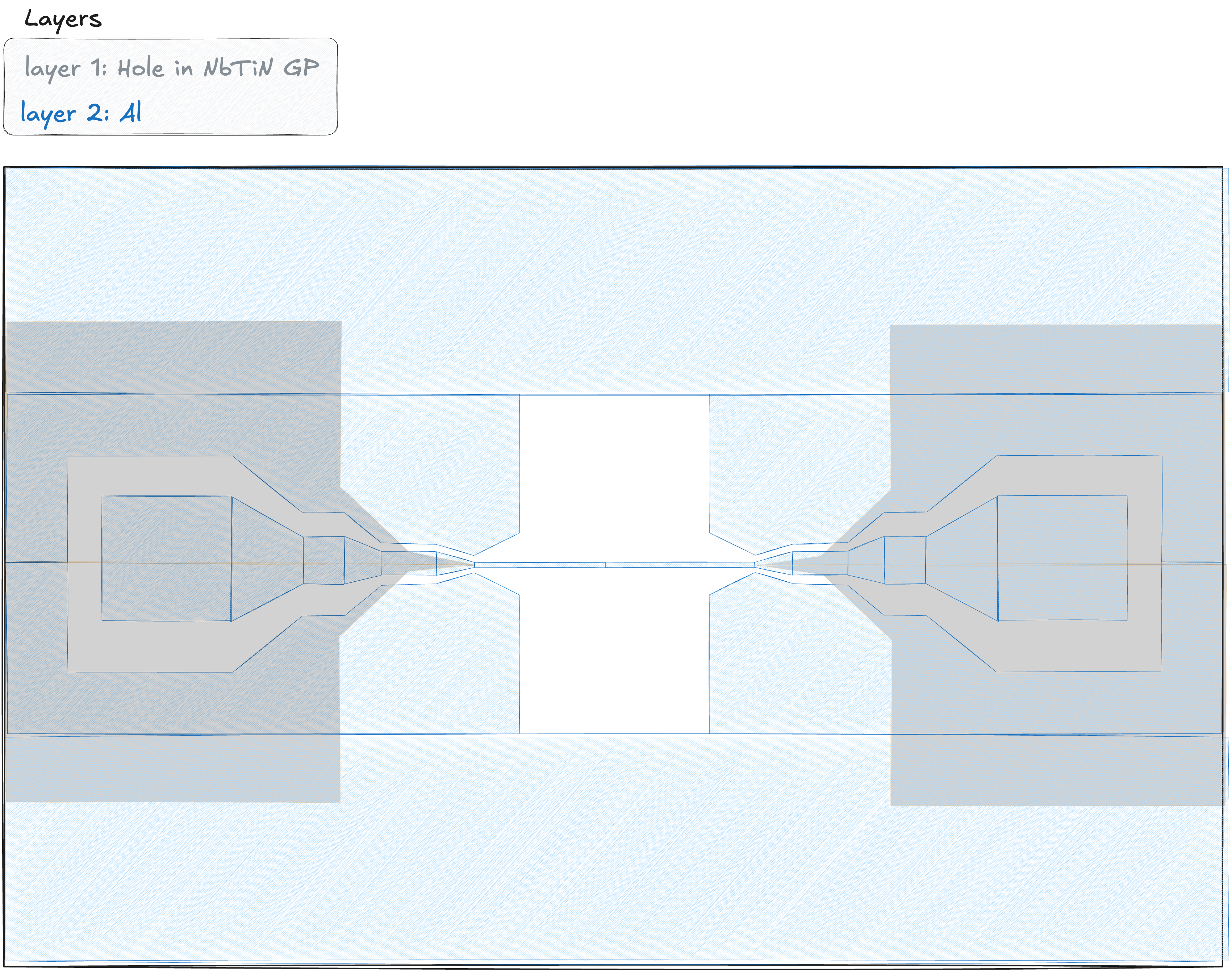
Put them together into the complete shape:
class MSLHalves(rai.Compo):
    """Two halves of the MSL structure joined together with a signal line"""
    def _make(self):
        left = MSLHalf().proxy()
        right = MSLHalf().proxy()

        right.vflip()

        right.snap_right(left)

        # Register subcompos
        self.subcompos.left = left
        self.subcompos.right = right

rai.show(MSLHalves())
And there we go! From here on out, the next step would be to define some usful marks and allow setting custom dimensions for each part of the tapered CPW using Options. These are left as an exercise to the reader.